Most modern and in particular higher end models use digital control and temperature sensors to more precisely and efficiently control the cooling cavity. The PCB is the electronics board where all the input and out put connections of the control system go and when the programming software it containing.
The PCB with monitor temperature within the fridge freezer cavity and will turn the refrigeration system on and off to maintain the correct set temperature.
Most PCB digitally controlled fridge freezer units have a built in error code list which can help in fault finding diagnostics.
The PCB is the main part of the system and is an electronic centre that controls the temperatures of the fridge with more precision as compared to the older on-off electro-mechanical thermostats. The PCB monitors the inputs ie Thermistor inside fridge cavity controls the output ie compressor on off and power in linear compressors to keep the desired temperature in the fridge freezer.
You can test a lot of the components on a PCB as they are mostly simple electrical components for when it comes to control and program chips these are not rally replaceable.
When a PCB fails it can be anything from a single function failing to complete system failure and no lights or functioning, it could trip the electric or RCD or it could flash up a code so a lot of fault finding can be needed to call the expensive PCB as the fault.
PCBs can have single component failure or a track on the board have open circuited.
Common symptoms of a PCB failure are No power , NO cooling , error codes and not carrying out a specific function.
Test for power coming into the PCB , check for any fuses as well. You can also test the relays or bypass them by removing the outlet side terminals and jumping them to see if the oven elements now operate.
Sometimes heat or water can damage a PCB board and timer will need replacing but you may need to look for the cause of heat or water.
PCB , Capacitors - MOV - Resistors - Diodes - Relay - Speaker - Transistors
Above is a basic timer PCB all components can be tested and replaced with a little know how, see video below for basics of component testing.
Testing electronic components with a multimeter ( Basics )
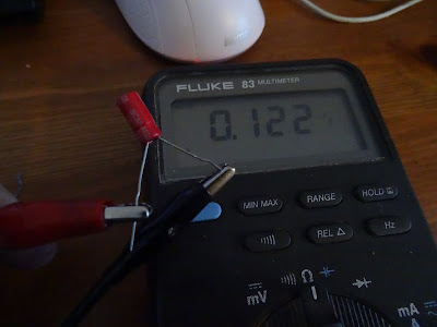
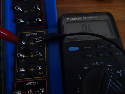
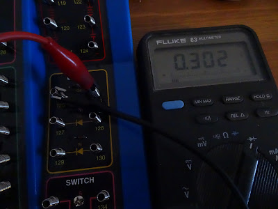
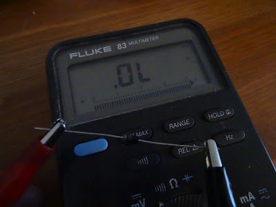
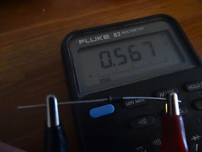
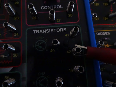
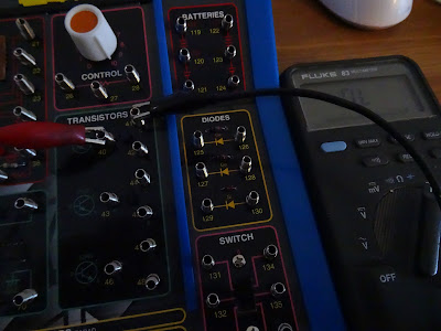
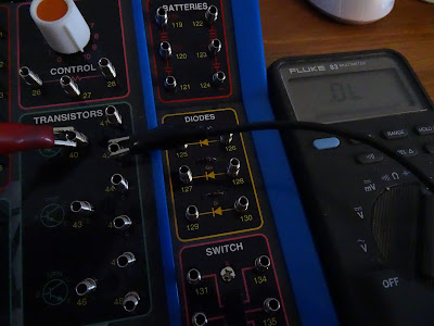
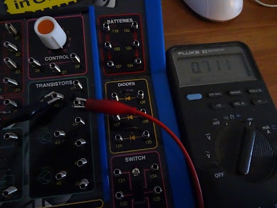
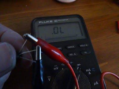
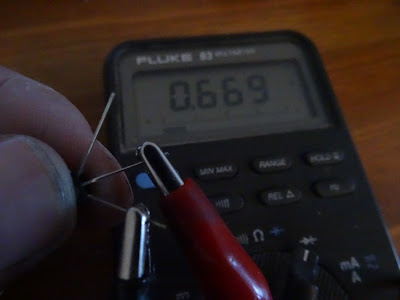
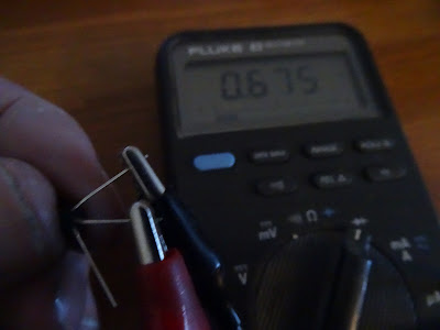
Testing basic electronic components, i use an electronics learning board to practice testing i recommend getting one if your a beginner here i show you some testing on the learning board and real components.
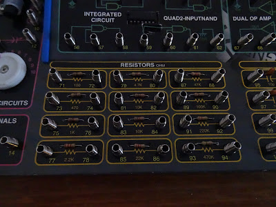
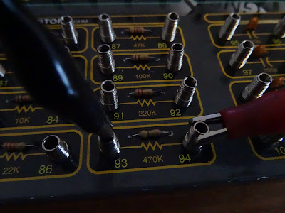
First ill start with resistances on the learning board here is a photo of all the resistances on this board from 100 ohms to 0.470 M ohms.
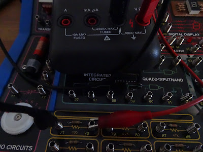
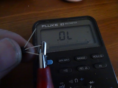
So set your meter up to read ohms on the selector dial and the leads in correct terminals.
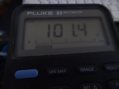
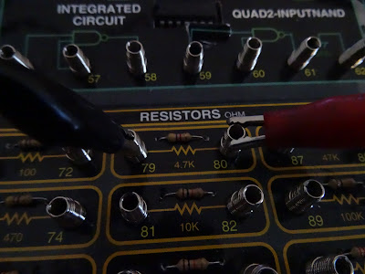
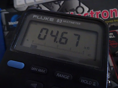
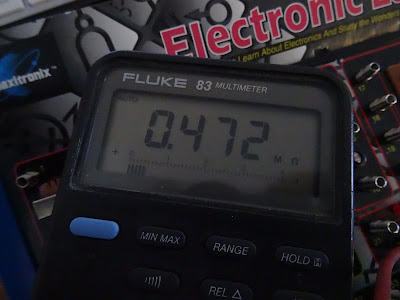
Connect across each resistor to take a reading .
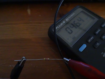
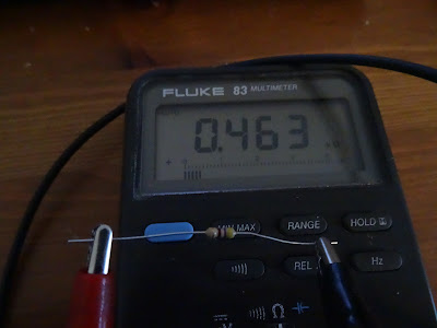
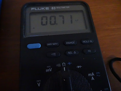
Ill do a few more measurements on resistances and on real resistance components






No comments:
Post a Comment